
 English
 Russian
 French
 Spanish
 Portuguese
 Italian
 Arabic
 German

Hot News
-
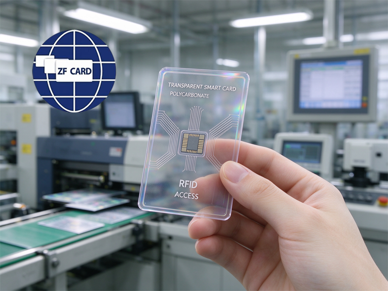 How to Design a Transparent Window PC Card (Without Killing the NFC Read Range) Nov 07,2026
-
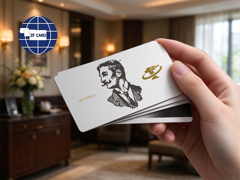 How Much Do Custom RFID Hotel Key Cards Cost from Manufacturers Nov 04,2026
-
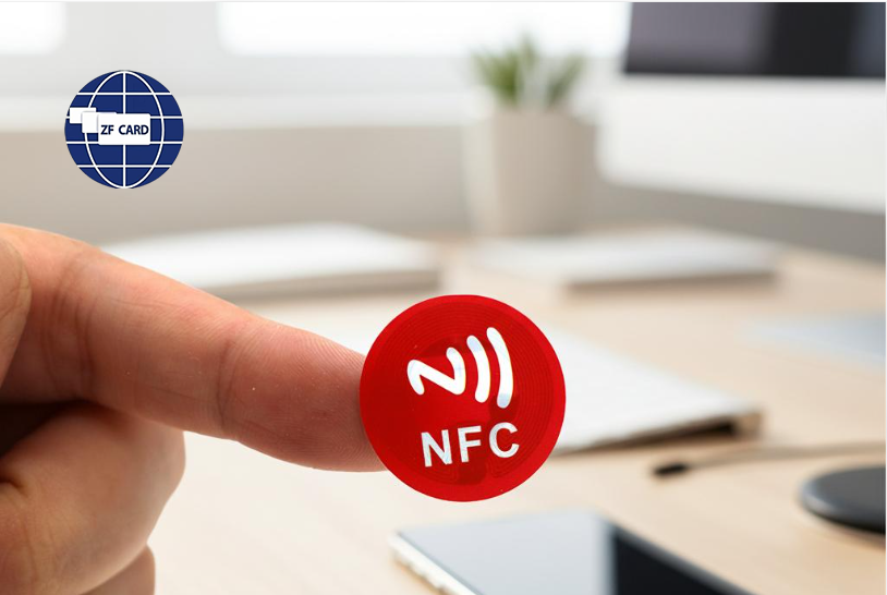 How to Find Reliable NFC Tag Sticker Suppliers for Bulk Custom Orders Nov 03,2026
-
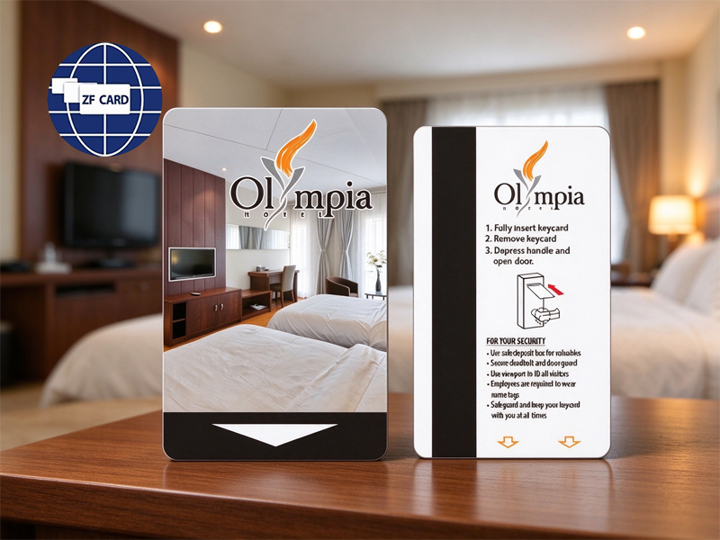 What to Know Before Ordering Custom Wood RFID Cards for Access Control Oct 29,2026




How to Design a Transparent Window PC Card (Without Killing the NFC Read Range)
A transparent window is the quickest way to make a premium member card, a hotel VIP key, or a brand credential look like something worth keeping. It shows the chip, a hologram, a security thread, or simply daylight through the card, and it reads as high-end manufacturing in a way surface printing never does. It is also the fastest way to destroy contactless performance if the design is handled casually. On a transparent polycarbonate smart card the real question is not whether the window looks good, but how much antenna area it costs.
Every square millimetre of window is antenna area removed from a 13.56 MHz loop, and the loss is not linear. The material choice is settled before the design starts, though. Polycarbonate is what makes a transparent polycarbonate smart card practical: it is optically clear, impact-resistant, stable across a wide temperature band, and it can be laminated at the temperatures and pressures a multi-layer card requires. It also survives laser personalisation, which matters for member photos and serial numbers buried under a clear layer.

There are four practical ways to build the window. The first is a routed or milled aperture, where material is cut away and a clear PC insert is bonded in. The second is a die-cut window with a clear patch laminated over it, which is cheaper but leaves a visible edge. The third is a full clear body with printed opaque layers only where artwork is needed. The fourth is a partial clear patch layered inside an otherwise opaque card. Each route changes the antenna constraint differently.
That constraint is the core of the project. An NFC antenna is a conductive loop tuned to resonate at 13.56 MHz, and its read range comes from the area enclosed by that loop. Put a window in the middle of a transparent polycarbonate smart card and the loop must route around it, which means less enclosed area, lower inductance, and a shorter read distance. On a 30 mm window in a CR80 card, the loop typically loses between a fifth and a third of its usable area.
The first compensation is geometric: route the antenna around the window with the largest outer diameter the card edge allows, and use the full perimeter rather than a tight inner loop. A loop hugging the CR80 edge keeps more area than an inner loop that clears a wide margin. Where the window is small, an antenna that wraps the whole card and crosses behind the window on the opposite layer can recover most of the loss, provided the two halves are joined reliably.
The second compensation is electrical. Fewer turns and less area mean lower inductance, so the matching capacitor and the chip input need to be retuned together rather than assuming a stock inlay will work. Designers who cut a window into a standard inlay and expect it to read usually discover the failure at sampling. Retuning is a design activity, not a production tweak, and it should happen before tooling is cut.
The third compensation is the chip. Higher-sensitivity parts buy back range: NTAG 215 and NTAG 216 tolerate weaker fields better than the smallest NTAG 213 variants, and MIFARE DESFire EV3 performs well in constrained designs. For access control, a reader with adjustable output power can absorb part of the loss. What cannot be compensated is a design that combines a low-sensitivity chip, a small loop, and a large window at once.
Transparent conductive films look like the elegant answer and usually are not. Indium tin oxide and silver nanowire films can carry the antenna invisibly across a window, but they have far higher sheet resistance than copper or aluminium, which lowers the Q factor of the loop and can hurt read range more than the window itself. They also add cost, process complexity, and a new failure point at the chip connection. For most member and hotel cards, an opaque antenna routed around the window is the better choice.
The window insert material has its own effect. A clear PC insert is the default and behaves close to the card body. But an insert with a different dielectric constant, or an air gap left by a loose bond, shifts the resonance frequency of the loop and can detune a design that tested perfectly on paper. Lamination pressure, adhesive thickness, and the symmetry of the layer stack all matter, because an asymmetric stack warps, and a warped card changes the antenna geometry across the batch.
Chip placement is the next decision that is easy to get wrong. The module must sit in an opaque area, not under the window, because the clear patch exposes the module and its bonding wires to view and to mechanical stress. Placing it near the window edge also puts it in the highest-flex zone, where delamination starts. The safer pattern is a window offset toward the top of the card and the chip module in the lower third, connected by a short antenna lead.
Printing on a transparent polycarbonate smart card has to respect the window from the first proof. Opaque white ink under the artwork is what makes colours read correctly, and any area left unprinted will look different from the window itself. Silk-screen layers should stop short of the window edge with a clean margin, and the window should never sit where a magnetic stripe, scratch panel, or signature panel needs to land. Proofs on a clear substrate also reveal registration drift that a white-backed proof hides.
Testing is the step that decides whether the design ships. Measure read distance on the finished card, not on the bare inlay, and measure it on both an iPhone and a mid-range Android handset, since NFC antenna placement differs across models. Test before and after lamination, after a bend cycle, and after the card has sat in a warm car. A design that reads at 3 cm when flat but 1 cm after a week in a wallet is not ready for a hotel rollout.
This is the engineering work ZF Card (Zhanfeng) has done for twenty years as a China-based original polycarbonate card manufacturer. We produce transparent polycarbonate smart cards for hotel groups, private clubs, and brand credential programs in more than a hundred countries, with routed apertures, clear inserts, full-clear bodies, and printed opaque frames, using MIFARE Classic 1K, DESFire EV3, and NTAG 21x chips. Our in-house line covers PC lamination, window routing, clear-patch bonding, antenna design support, printing, encoding, and read-range testing under one roof.
Because the window and the antenna compete for the same space, we tune the loop and the matching circuit for the specific window geometry before tooling is cut, then send a physical sample for you to tap on your own readers. We hold ISO 9001 and ISO 14001 certification, keep RoHS and REACH documentation ready, and test every batch on iPhone and Android before packing. English-speaking engineers walk through window size, chip choice, and read-distance trade-offs before the quote.
The only fair way to judge a window card is to hold it against daylight and tap it on your own reader. ZF Card ships free sample packs to hotel groups, membership brands, and access-control integrators worldwide — you cover the courier, and we send clear-insert and full-clear variants printed with your artwork and encoded to your chip spec.
Tell us your window dimensions, your chip preference, your reader model, and your projected annual volume, and we will reply within one business day with a read-range assessment, a firm lead time, and a factory-direct quote.
Stop choosing between a card that looks premium and a card that opens the door — request your free transparent polycarbonate smart card sample today and see the clarity, the lamination, and the read that twenty years of specialized card manufacturing delivers.
-
 Design your card for free
Get Free Design
-
 Free Sample Cards
Get Free Sample
-
 24 hours online service
Contact Us
-
Office Phone
+86 189-3398-5004
-
E-mail
mailto:mary@zfcards.com
-
Office Phone


